
- Home
- Company
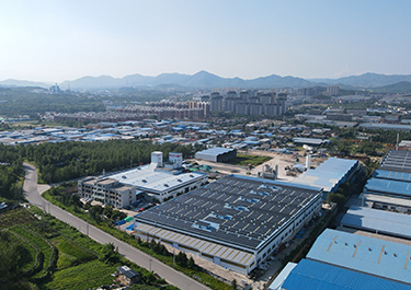 Our FactoryWe have a team of more than 30 talented geotechnical material R&D experts and a 30,000 square meter advanced modern intelligent manufacturing plant.
- Products
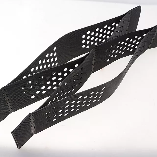 Geocell is a three-dimensional mesh structure made of high-strength polymer sheets (such as HDPE, PP, etc.) through ultrasonic welding. When unfolded, it presents a three-dimensional grid shape.
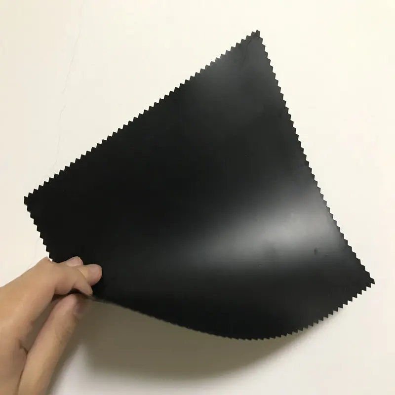 Geomembrane is a thin, extremely low-permeability sheet material made from high-molecular-weight polymers (high-density polyethylene, linear low-density polyethylene).
- Blog
- Contacts
Top 8 Geotextile Protection Tips to Extend Geomembrane Life


A geomembrane is only as durable as the system that surrounds it. Even the highest-grade HDPE liner—with a design life of 50 to 100 years—can be rendered useless within a single construction season if it is punctured, abraded, or stress-cracked during installation. And the data is sobering: an estimated 60–80% of geomembrane damage occurs during the installation phase—not during decades of service.
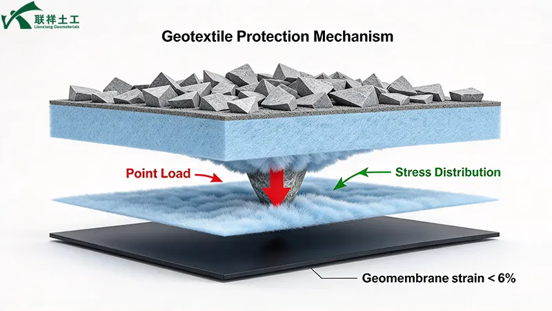
The solution is not a thicker geomembrane. It is a properly designed and specified geotextile protection layer—a nonwoven needle-punched cushion that absorbs point loads, dissipates stress concentrations, and acts as a sacrificial barrier against puncture and abrasion. When designed correctly, a cushion geotextile can limit the strain imposed on the geomembrane to below 6%—a critical threshold for preventing long-term stress cracking.
This guide provides the top 8 geotextile protection tips to extend geomembrane service life—backed by GSI design methodology, ASTM test standards, and documented field performance data.
Tip 1: Recognize the True Scale of the Puncture Threat
Before selecting a protection geotextile, it is essential to understand where geomembrane damage actually occurs. The statistics are clear—and they point directly to the protection layer as the decisive variable.
According to defect frequency analysis for polymeric geomembranes in landfill applications:
| Defect Source | Defects per Hectare | Percentage of Total |
|---|---|---|
| Inadequate seams | 4 | ~21% |
| Mechanical damage during installation | 1 | ~5% |
| Mechanical damage during placement of overlying material | 14 | ~74% |
| Total | 19 | 100% |
Source: Geosynthetic Society defect frequency analysis
Nearly three-quarters of all geomembrane defects originate during the placement of the overlying material—the drainage aggregate, cover soil, or waste mass placed directly above the liner. A properly specified cushion geotextile is the primary defense against this failure mode.
Field data: A survey of electrical damage detection systems across more than 3 million square meters of installed geomembranes confirmed that mechanical damage during cover placement is consistently the dominant defect mechanism—and that protection geotextiles are the most effective mitigation measure.
Key takeaway: If your project involves placing angular drainage aggregate, crushed stone, or any coarse material above a geomembrane, a protection geotextile is not optional. It is the difference between a verified barrier and an unverified assumption.
Tip 2: Select the Right Mass Per Unit Area – The Single Most Important Specification
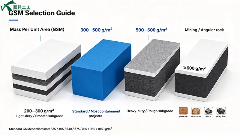
For pure puncture protection, mass per unit area (GSM) is the single most important property of a cushion geotextile. Heavier fabrics are thicker, provide more physical buffer zone, and allow fibers more room to deform and absorb load.
Common specification grades for geomembrane protection:
| GSM (g/m2) | Typical Application | Subgrade Condition |
|---|---|---|
| 200–300 | Light-duty protection, well-prepared subgrade | Smooth, compacted soil |
| 300–500 | Standard protection—most containment projects | Moderate subgrade, standard aggregate |
| 500–600 | Heavy-duty protection | Rough subgrade, angular aggregate |
| ≥600 | Mining, landfill with angular subgrade | Highly angular rock, extreme conditions |
Source: Industry specification guidance for HDPE liner protection
GSI recommended MARV (Minimum Average Roll Values) for protection geotextiles:
The Geosynthetic Institute design manual specifies commercially available needle-punched nonwoven protection geotextiles at the following mass denominations: 335, 405, 540, 675, 810, 950, and 1,080 g/m2. Specifying an intermediate, non-standard mass (for example, 470 g/m2) may require custom manufacturing and significantly increase cost.
| Mass (g/m2) | Thickness (mm, min) | Pin Puncture (kN, MARV) | Trapezoid Tear (kN, MARV) |
|---|---|---|---|
| 335 | 2.6 | 0.80 | 0.4 |
| 405 | 2.9 | 0.90 | 0.5 |
| 540 | 4.1 | 1.1 | 0.6 |
| 675 | 4.8 | 1.2 | 0.8 |
| 810 | 6.6 | 1.8 | 1.1 |
Source: GSI protection geotextile MARV table (SI units)
Construction tip: For most containment projects—landfills, reservoirs, canals—specify a cushion geotextile in the 300–500 g/m2 range. For mining tailings or landfill cells with angular, poorly prepared subgrades, increase to ≥600 g/m2.
Tip 3: Apply the GSI Design Equation – Don't Guess, Calculate
Selecting a protection geotextile by "rule of thumb" is a recipe for either under-protection (leading to puncture) or over-specification (leading to unnecessary cost). The Geosynthetic Institute has developed a rigorous design methodology that relates allowable pressure, geotextile mass, and protrusion height.
The GSI allowable pressure equation:
Pallow = (50 + 0.00045 × M / H2) × [1 / (MFS × MFPD × MFA)] × [1 / (RFCR × RFCBD)]
Where:
| Variable | Definition | Typical Values |
|---|---|---|
| M | Geotextile mass per unit area (g/m2) | 335–1,080 g/m2 |
| H | Effective protrusion height (m) | 0.006–0.038 m (6–38 mm) |
| MFS | Modification factor for protrusion shape | Angular: 1.0; Subrounded: 0.5; Rounded: 0.25 |
| MFPD | Modification factor for packing density | Isolated: 1.0; Dense 38mm: 0.83; Dense 25mm: 0.67 |
| RFCR | Reduction factor for creep | ≥1.0 |
| RFCBD | Reduction factor for chemical/biological degradation | Mild leachate: 1.1; Moderate: 1.3; Harsh: 1.5 |
Source: GSI geomembrane protection design method
Minimum global factors of safety against puncture (FSP = Pallow / Pact):
| Protrusion Height (mm) | Minimum Global FS Against Puncture |
|---|---|
| 6 | 3.0 |
| 12 | 3.0 |
| 25 | 3.0 |
| 38 | 3.0 |
Source: Florida DEP design criteria for cushion geotextiles
Key takeaway: The GSI equation demonstrates that allowable pressure scales linearly with geotextile mass but inversely with the square of protrusion height. A 25 mm protrusion reduces allowable pressure to roughly 1/17th of what a 6 mm protrusion allows at the same geotextile mass. This is why subgrade preparation (Tip 7) and mass selection (Tip 2) must be considered together.
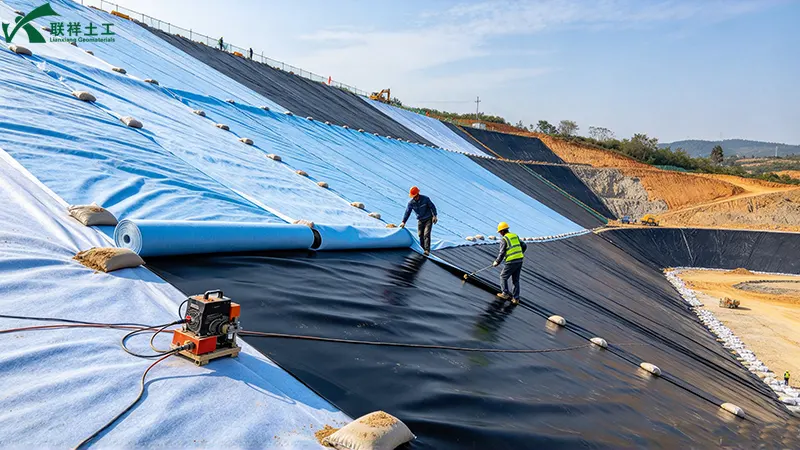
Tip 4: Specify Nonwoven Needle-Punched Geotextile – Not Woven
The fiber structure of a cushion geotextile determines how effectively it can dissipate point loads. For geomembrane protection, the material of choice is unequivocally a nonwoven needle-punched geotextile.
Why nonwoven needle-punched structure excels:
- Three-dimensional fiber network: Countless randomly oriented fibers interlock to form a thick, compressible cushion
- Stress distribution: Point loads are shared across thousands of fibers rather than concentrated on a few high-strength yarns
- Strain limitation: The cushioning effect keeps geomembrane strain below 6%—the threshold beyond which long-term stress cracking risk increases significantly
- Sacrificial abrasion resistance: The fibrous surface absorbs frictional wear from aggregate placement and dynamic loading
Woven geotextile limitation: Woven fabrics have a regular, grid-like structure with limited thickness and compressibility. They are designed for tensile reinforcement and separation—not for cushioning. A woven geotextile cannot provide the stress-dissipation mechanism required for geomembrane protection.
Material specification: Specify virgin polypropylene (PP) or polyester (PET) needle-punched nonwoven. Recycled-fiber nonwoven products exhibit variable puncture performance and are not recommended for critical containment projects.
Tip 5: Meet Minimum Puncture and Tear Resistance Thresholds
Beyond mass per unit area, specific mechanical property thresholds must be met to ensure the protection geotextile survives installation and provides reliable long-term cushioning.
Recommended minimum mechanical properties for protection geotextiles:
| Property | Test Method | Minimum Requirement | Why It Matters |
|---|---|---|---|
| Pin puncture strength | ASTM D4833 | ≥0.80 kN (335 g/m2) to ≥1.8 kN (810 g/m2) | Resists puncture from subgrade protrusions |
| Trapezoid tear strength | ASTM D4533 | ≥0.4 kN (335 g/m2) to ≥1.1 kN (810 g/m2) | Prevents tear propagation during installation |
| Grab tensile strength | ASTM D4632 | ≥1.1 kN (335 g/m2) to ≥2.5 kN (810 g/m2) | Ensures survivability during handling |
| CBR puncture | ASTM D6241 | 1.5–6.0 kN (depending on GSM) | Alternative index for puncture resistance |
Sources: GSI MARV table; industry specification data
Regulatory reference: The EPA has referenced minimum values of 170 lbs (0.76 kN) pin puncture (ASTM D4833) and 300 lbs (1.33 kN) grab tensile (ASTM D4632) for protection geotextiles in certain containment applications. However, these are floor values—the GSI design method may dictate higher requirements based on site-specific protrusion height and loading conditions.
Construction tip: Always request ASTM test reports for the specific production lot—not generic "typical values" from a product brochure. Verify that the reported values are MARV (Minimum Average Roll Values) , not single-point test results.
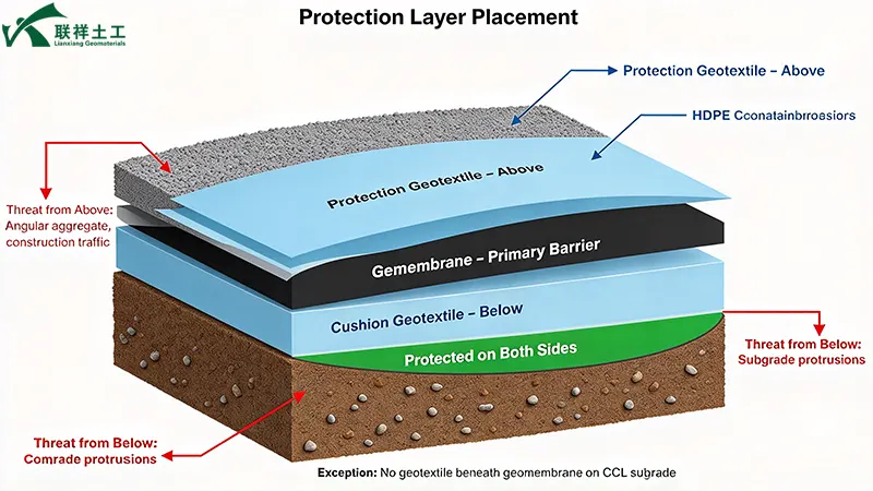
Tip 6: Design the Protection Layer for Both Sides of the Geomembrane
Geomembrane puncture can occur from below (subgrade protrusions) and from above (drainage aggregate, cover soil, or waste). A comprehensive protection design addresses both threat vectors.
Beneath the geomembrane—subgrade protection:
- Threat: Stones protruding from a poorly prepared subgrade, or stones dislodged during geomembrane dragging
- Solution: Place a cushion geotextile directly on the prepared subgrade before geomembrane deployment
- Design consideration: The required GSM is a function of the effective protrusion height (H) and the protrusion shape factor (MFS) —angular stones require the full mass calculated by the GSI equation, while rounded stones allow a reduction
Above the geomembrane—cover protection:
- Threat: Angular drainage gravel, crushed stone, or waste materials placed directly on the liner; also construction traffic and equipment during cover placement
- Solution: Place a protection geotextile over the geomembrane before placing any overlying material
- Design consideration: For drainage layers (common in all landfills), a nonwoven needle-punched geotextile provides significant puncture protection
Critical warning: If the subgrade is a compacted clay liner (CCL) , a geotextile cannot be used beneath the geomembrane. Isolated stones must be physically removed. The geotextile protection strategy applies to soil or granular subgrades—not to CCL.
Tip 7: Control Subgrade Protrusion Height Before Specifying Geotextile
The GSI design equation makes one point unmistakably clear: protrusion height (H) has a squared effect on allowable pressure. Doubling the protrusion height from 6 mm to 12 mm reduces allowable pressure by a factor of four at the same geotextile mass. Tripling it to 18 mm reduces it by a factor of nine.
| Protrusion Height | Relative Allowable Pressure | Implication for Geotextile Mass |
|---|---|---|
| 6 mm | 1.0 (baseline) | Standard mass (e.g., 405 g/m2) |
| 12 mm | 0.25 (75% reduction) | Must quadruple mass or remove protrusions |
| 25 mm | ~0.058 (94% reduction) | Impractical to compensate with mass alone |
Calculated from the GSI equation (M/H2 term)
Practical subgrade preparation requirements:
- Remove all stones, roots, and debris from the upper 150 mm (6 inches) of subgrade
- Proof-roll the subgrade to identify soft spots and protrusions
- Compact to 90–95% of standard Proctor density
- For rocky subgrades where complete removal is impractical, specify a higher-GSM geotextile (≥600 g/m2) and a thicker cushion layer
Key takeaway: The most cost-effective protection strategy is not the heaviest geotextile—it is a well-prepared subgrade combined with a properly sized cushion geotextile. Spending on subgrade preparation often reduces the required geotextile mass and delivers superior long-term performance.
Tip 8: Protect the Protection Layer – Installation and Long-Term Integrity
A cushion geotextile that is damaged during installation cannot protect the geomembrane beneath it. The protection layer itself must be installed with care and verified before it is covered.
Installation best practices for protection geotextiles:
- Surface preparation: Ensure the subgrade (or geomembrane surface) is free of debris, moisture, and loose material before deploying the geotextile
- Overlap: Maintain a minimum overlap of 300 mm (12 inches) between adjacent geotextile panels
- Anchoring: Secure the geotextile against wind uplift and displacement during subsequent construction
- Traffic control: Minimize foot and equipment traffic on the installed geotextile; use designated access paths if necessary
- Immediate covering: Place the overlying material (drainage aggregate, cover soil) as soon as practical to prevent UV degradation and wind damage
- Inspection: Inspect the geotextile for tears, punctures, or displacement before placing overlying material—repair any damage immediately
Long-term performance verification: For critical containment projects, consider electrical leak location (ELL) surveys after placement of the overlying material. This verifies that neither the geomembrane nor the protection system was compromised during cover placement—the stage responsible for approximately 74% of all defects.
Cost perspective: Industry experience consistently shows that the cost of a protection geotextile is marginal compared to the risk of a leak. In one documented case, a reservoir project omitted the protection geotextile to save cost—and incurred repair expenses ten times the geotextile cost after the liner was punctured during backfilling.
Quick Reference: Top 8 Geotextile Protection Tips at a Glance
| # | Tip | Key Data / Requirement |
|---|---|---|
| 1 | Recognize the puncture threat | ~74% of defects occur during cover placement (14 of 19 per hectare) |
| 2 | Select correct mass per unit area | 300–500 g/m2 standard; ≥600 g/m2 for angular subgrade |
| 3 | Apply GSI design equation | Pallow ∝ M / H2; FSpuncture ≥ 3.0 |
| 4 | Specify nonwoven needle-punched | 3D fiber network; limits geomembrane strain to <6% |
| 5 | Meet puncture/tear thresholds | Pin puncture ≥0.80–1.8 kN (ASTM D4833); MARV values |
| 6 | Protect both sides | Cushion below geomembrane + protection above; CCL exception |
| 7 | Control protrusion height | H2 effect: 12 mm reduces allowable pressure 75% vs. 6 mm |
| 8 | Protect the protection layer | 300 mm overlap; ELL survey after cover placement |
Conclusion
A geomembrane's service life is determined not only by its own material quality but by the protection system that surrounds it. The data is unambiguous: nearly three-quarters of all defects occur during the placement of overlying materials—the exact stage that a properly designed cushion geotextile is intended to protect.
Written by
SHANDONG LIANXIANG ENGINEERING MATERIALS CO., LTD.
Kyle Fan
WhatsApp:+86 139 5480 7766
Email:admin@lianxiangcn.com
-
WhatsApp
-
E-MailE-Mail:admin@lianxiangcn.com
-
WeChatWeChat:18554180188