
- Home
- Company
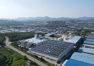 Our FactoryWe have a team of more than 30 talented geotechnical material R&D experts and a 30,000 square meter advanced modern intelligent manufacturing plant.
 - Products
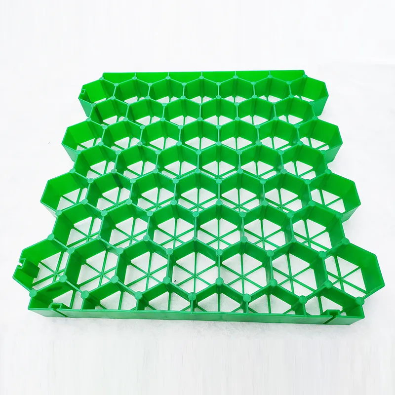
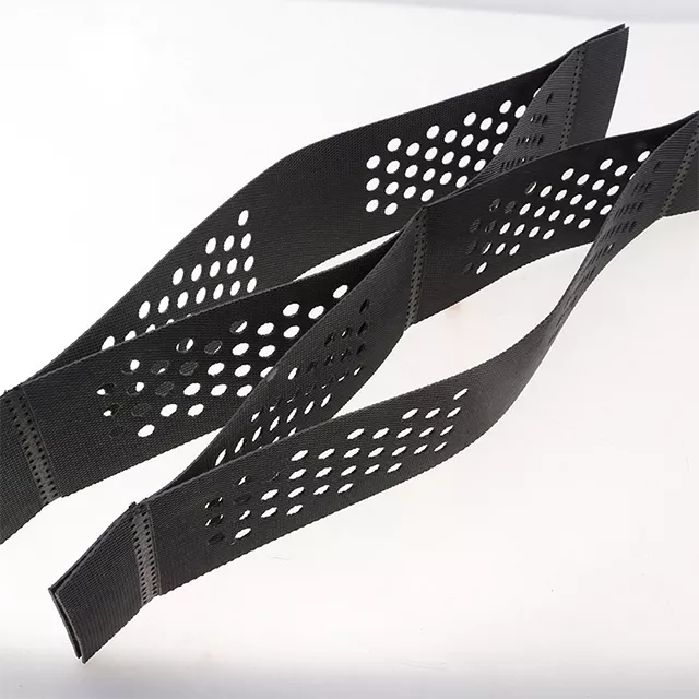 Geocell is a three-dimensional mesh structure made of high-strength polymer sheets (such as HDPE, PP, etc.) through ultrasonic welding. When unfolded, it presents a three-dimensional grid shape.
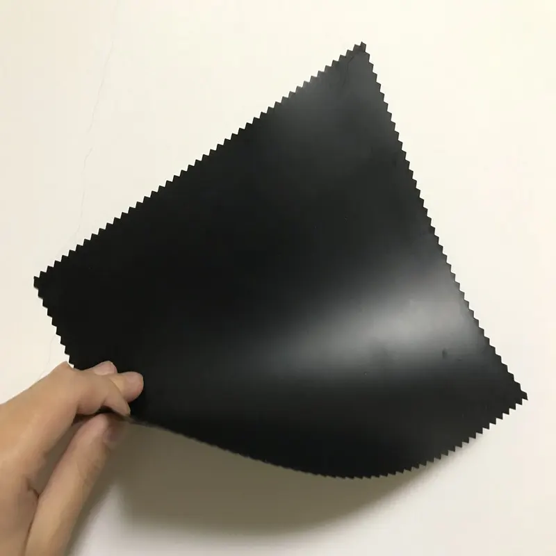 Geomembrane is a thin, extremely low-permeability sheet material made from high-molecular-weight polymers (high-density polyethylene, linear low-density polyethylene).
 - Blog
- Contacts
Landfill Liner Geomembrane: Top 8 Design & Installation Tips 2026


A landfill liner is not just a construction component-it is the primary environmental barrier between decades of accumulated waste and the groundwater beneath our feet. When it fails, the consequences are measured not in dollars alone, but in contaminated aquifers, public health risks, and regulatory penalties that can exceed $70,000 per violation.
The good news? Modern HDPE geomembrane liner systems, when properly designed and installed, can reduce contaminant flux by 4 to 6 orders of magnitude compared to natural clay soils alone. Electrical leak location surveys on operational cells routinely show zero to fewer than 5 leaks per hectare when installers follow best practices.
Here are the top 8 design and installation tips you need to know for landfill liner geomembrane systems in 2026-backed by regulatory standards and hard performance data.
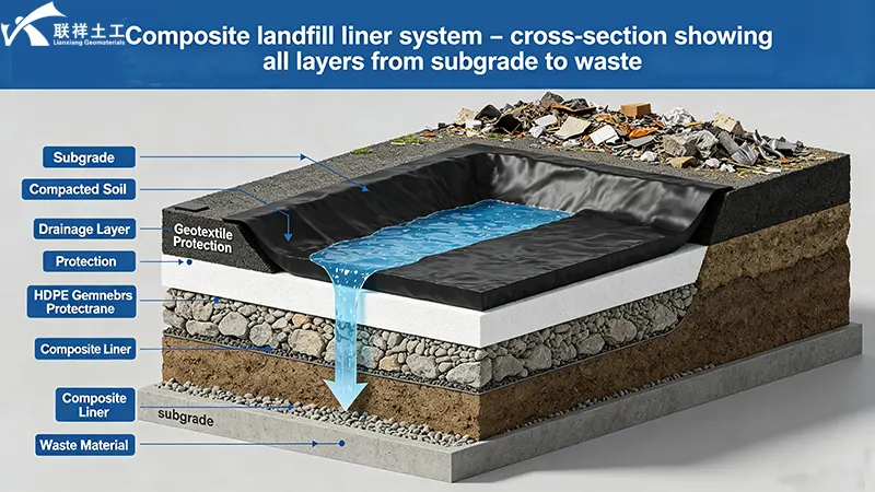
Tip 1: Design for Double Protection – The Composite Liner System
The days of single-layer liners are long gone. Under the United States EPA Subtitle D regulations (40 CFR Part 258), new municipal solid waste landfills must incorporate a composite liner consisting of:
| Component | Specification |
| Upper component | Flexible membrane liner (FML), typically 1.5 mm (60 mil) HDPE geomembrane |
| Lower component | At least two feet (0.6 m) of compacted soil with hydraulic conductivity <= 1 × 10⁻⁷cm/s |
The same principle applies globally:
- EU Landfill Directive (1999/31/EC) --> requires at least one hydraulic barrier plus geological barrier
- Canada (Ontario Regulation 232/98) --> composite liner plus leachate collection
- Australia (ANZECC guidelines) --> double-liner systems common for hazardous waste cells
For higher-risk applications, a double composite liner system is increasingly standard-consisting of a geomembrane, a geosynthetic clay liner (GCL), another geomembrane, and a compacted clay layer. Double-liner systems provide a high level of protection to the environment against potential impacts caused by leachate leakage.
Today's recommended complete landfill liner system (from bottom to top) includes:
- 1. Prepared subgrade / foundation soil
- 2. Secondary leachate collection / leak detection layer (for double-liner cells)
- 3. Secondary geomembrane (double-liner systems)
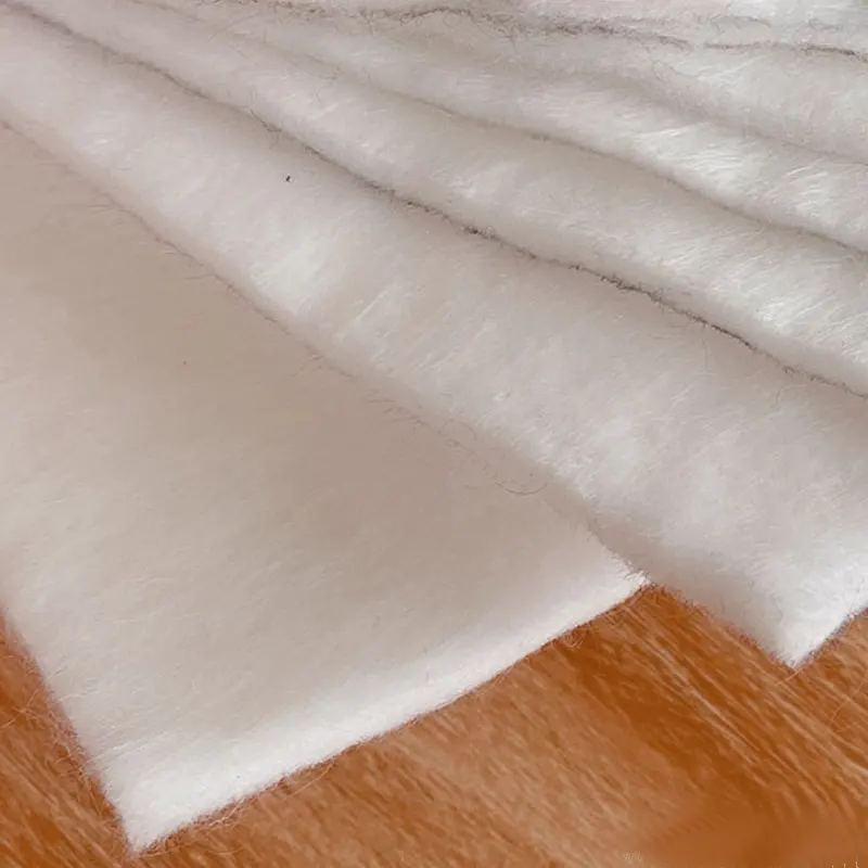
- 4. Secondary drainage / cushion geotextile
- 5. Compacted clay liner (CCL) or geosynthetic clay liner (GCL)
- 6. Primary geomembrane (almost always HDPE, >=1.5 mm)
- 7. Primary leachate collection and removal system (LCRS) – granular drainage layer + perforated HDPE collection pipes
- 8. Protective geotextile cushion
- 9. Waste / operations layer
Key takeaway: A single liner is only suitable for low-risk projects. For large landfills or high-risk applications, a double composite liner system is the industry standard.
Tip 2: Specify the Right Thickness – 1.5mm vs. 2.0mm
HDPE geomembrane thickness is not a matter of preference-it is a matter of regulation and risk assessment.
The minimum standard: Under EPA Subtitle D, HDPE geomembranes in landfill liner systems must be at least 60 mil (1.5 mm) thick.
For hazardous waste landfills: RCRA Subtitle C (40 CFR 264/265) requires 2.0 mm (80 mil) HDPE geomembranes.
| Parameter | 1.5 mm (60 mil) | 2.0 mm (80 mil) |
| Puncture resistance (ASTM D4833) | >=300 N | >=400 N |
| Tear resistance (ASTM D1004) | >=125 N | >=150 N |
| Oxygen transmission | Higher | Lower (OTR < 10 cc/m²/day) |
| Service life | 50+ years | 100+ years |
| Typical application | MSW landfills | Hazardous waste, waste height >30m |
The 2.0 mm geomembrane provides superior puncture resistance (>=400 N) and lower oxygen diffusion to protect the underlying GCL. For landfills with waste heights exceeding 30 meters, 2.0 mm thickness is recommended.
Key takeaway: 1.5 mm is the minimum for MSW landfills. 2.0 mm is required for hazardous waste and recommended for high-stress applications.
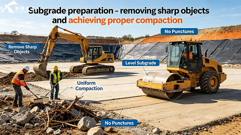
Tip 3: Prepare the Subgrade Like Your Liner Depends on It-Because It Does
Subgrade defects account for approximately 37% of all liner failures. This is the single most preventable cause of geomembrane failure.
Subgrade preparation requirements:
| Parameter | Requirement |
| Surface flatness | <=3mm deviation over 3m (ASTM F710) |
| Stone size | Remove all rocks > 20mm diameter |
| Compaction | 90–95% of standard Proctor density |
| Moisture content | Within ±2% of optimum |
| Surface condition | No holes, depressions >1 inch in 12-inch width, no protrusions >1/2 inch |
| Debris removal | Remove all stones, roots, debris, and sharp objects from upper 6 inches of subgrade |
Additional requirements from New York State regulations:
Surface must be free of stones, organic matter, cracks, irregularities, protrusions, loose soil, and any abrupt changes in grade
When dealing with weak soils (CBR values below 3), add 6 to 12 inches of granular material for stabilization
Why this matters: Undetected subgrade flaws-sharp protrusions, voids, or uncompacted zones-create localized stress points that can puncture the geomembrane under the weight of hundreds of thousands of tons of waste.
Key takeaway: Spend the time on subgrade preparation. It accounts for nearly 40% of all failures-and it is entirely preventable.
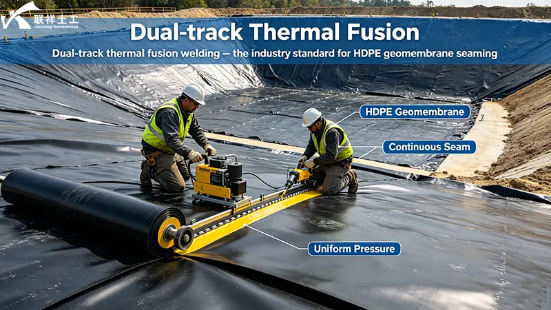
Tip 4: Master the Seaming – Where 80% of Leaks Originate
Approximately 80% of geomembrane leaks originate at seams. This is where installation quality makes or breaks the entire liner system.
Seaming requirements:
| Parameter | Requirement |
| Seam orientation | Parallel to the line of maximum slope (along, not across the slope) |
| Horizontal seams | Minimize; must be >5 feet from the toe of slope |
| Primary method | Dual-track thermal fusion welding |
| Extrusion welding | Minimized to the extent practical |
| Panel overlap | 75–100mm for smooth HDPE |
| Welding temperature | 400–500oC (adjust by thickness) |
| Welding speed | 1.5–3.0 m/min (dual-track) |
Seaming is prohibited when:
- Ambient air temperature (1m above geomembrane) is below 32oF (0oC)
- Surface temperature of geomembrane exceeds 158oF (70oC)
- Ambient air temperature exceeds 120oF (49oC)
- Sustained winds exceed 20 mph
- During precipitation
Before seaming, the seam area must be:
- Free of moisture, dust, dirt, debris, and foreign material
- Properly cleaned-dust contamination before welding is a root cause of seam failure
Personnel qualifications:
- Field crew foreman: Documented minimum of installing at least 50 acres of previous landfill or comparable systems, on minimum of five different projects
- Each welding machine operator: Certified by an approved certification program
Key takeaway: Seams are the weakest link. If you get the seams right, you've solved 80% of the leak problem.
Tip 5: Anchor It Right – Design for Pullout Resistance, Not Just Hold
Anchor trenches are not an afterthought-they are a critical structural element that prevents the entire liner system from sliding or pulling out under the weight of waste.
Design objective: The anchor trench should be designed so that the geomembrane pulls out before the geomembrane fails.
V-shaped anchor trenches are commonly used in MSW landfills. The main objective is to ensure safety against pullout failure in geomembrane liners.
Anchoring requirements:
- Construct anchoring system as shown on approved engineering drawings
- Divert surface water run-off away from the anchoring system
- Seam the primary and secondary geomembranes together at the anchor trench
Key considerations:
- Anchor trenches should always be pumped dry to prevent water seeping into the subgrade
- Water in anchor trenches can cause slope stability problems
The anchoring system must eliminate potential liquid leakage into the secondary leachate collection and removal system.
Key takeaway: Anchor trenches are not just for holding the liner in place-they are a critical barrier component that must be designed and constructed with the same care as the liner itself.
Tip 6: Install Leak Detection – Because You Can't Manage What You Can't Measure
You cannot fix a leak you don't know exists. Modern landfill liner systems incorporate leak detection systems that provide early warning of liner compromise.
Double-liner systems include a leak detection zone located between the primary and secondary geomembranes. This zone allows for:
- Monitoring of the upper liner's performance
- Early detection of leaks before they reach the environment
- Electrical leak location surveys to pinpoint the exact location of any breach
Electrical leak location methods detect and locate leaks in geomembrane liners by measuring the potential distribution above or under the liner. For double-lined landfills, detecting electrodes are typically arranged between the two liners (in the detection layer).
Performance data: Projects using rigorous CQA programs with electrical leak location surveys had an average of just 4 leaks per hectare, compared to 22 leaks per hectare for projects without rigorous CQA.
Key takeaway: A leak detection system is not optional-it is essential for verifying liner integrity and providing early warning of any issues.
Tip 7: Implement Rigorous QA/QC – The 4-Leak vs. 22-Leak Difference
Quality management on geomembrane installations is divided into two complementary sections:
| Component | Who Performs | Purpose |
| Construction Quality Control (CQC) | Installer | Checks welding parameters, maintains recording logs, performs initial testing |
| Construction Quality Assurance (CQA) | Third party | Assesses compliance with plans and specifications |
The testing program must include:
| Test Type | Method | Application |
| Non-destructive | Air pressure test | Fusion seams |
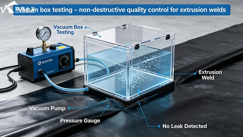
| Non-destructive | Vacuum test | Extrusion seams |
| Destructive | Peel strength | Seam samples |
| Destructive | Shear strength | Seam samples |
Specific test parameters:
- Air channel test pressure: 30 psi (2 bar), hold 5 minutes, decay <=20%
- Peel test acceptance: >=31 N/cm or 50% of parent sheet
- Destructive samples: Every 150 meters
100% of all field seams must be non-destructively tested over their full length. For double fusion seams, air pressure testing is required.
The result: Projects with rigorous CQC and CQA programs consistently achieve leak densities of 4 or fewer leaks per hectare. Without rigorous QA/QC, that number jumps to 22 leaks per hectare.
Key takeaway: Rigorous QA/QC is not a cost-it is an investment that reduces leaks by a factor of 5.
Tip 8: Protect the Liner – From Installation to Cover
The geomembrane is most vulnerable during and immediately after installation. Protection measures are critical.
Material storage:
- All rolls must be enclosed in protective wrapping or covered with an opaque tarpaulin
- Protection from: direct sunlight, UV radiation, flames/welding sparks, temperatures >160oF, mud, debris, and other deleterious materials
- Storage location: stable, dry, well-drained
- Storage surface: free of sharp objects
During installation:
- Place a protective geotextile cushion over the geomembrane before placing the drainage layer
- The protective layer prevents puncture of the primary geomembrane during subsequent construction
- Minimize traffic on the exposed geomembrane
- Repair any damage immediately
Final cover:
- The multi-component barrier system-combined with active leachate pumping and gas collection-forms the core of the "dry tomb" landfill philosophy adopted by the EPA in 1991
- This approach minimizes liquid ingress and maximizes containment duration
Key takeaway: The best liner in the world will fail if it is punctured during subsequent construction. Protection layers are not optional.
Quick Reference: Top 8 Landfill Liner Tips at a Glance
| # | Tip | Key Requirement | Impact |
| 1 | Double Protection | Composite liner: 1.5mm HDPE + 0.6m compacted clay | 4–6 orders of magnitude reduction in flux |
| 2 | Right Thickness | 1.5mm minimum (MSW); 2.0mm required (hazardous) | >=400N puncture resistance for 2.0mm |
| 3 | Subgrade Prep | <=3mm/3m flatness; remove rocks >20mm; 95% compaction | Prevents 37% of failures |
| 4 | Master Seaming | Dual-track fusion; 400–500oC; 1.5–3.0 m/min | Seams cause 80% of leaks |
| 5 | Anchor Design | V-shaped trenches; pump dry; seam primary + secondary | Prevents pullout failure |
| 6 | Leak Detection | Double-liner system with detection zone | 4 leaks/ha vs. 22 leaks/ha |
| 7 | Rigorous QA/QC | 100% NDT + destructive samples every 150m | 5× reduction in leak density |
| 8 | Protect the Liner | Geotextile cushion; proper storage; immediate repairs | Prevents installation damage |
Final Thoughts
A landfill liner geomembrane system is only as good as its design and installation. The difference between a liner that performs for 50+ years and one that fails within a decade is not luck-it is attention to every detail, from subgrade preparation to seam testing to final cover placement.
Remember:
- 1.5 mm is the minimum for MSW landfills; 2.0 mm is required for hazardous waste
- Subgrade preparation prevents 37% of failures
- Seams cause 80% of leaks-master the welding
- Rigorous QA/QC reduces leaks by a factor of 5
- Composite and double-liner systems are the industry standard for a reason
The cost of doing it right is measured in thousands. The cost of doing it wrong is measured in environmental contamination, regulatory fines exceeding $70,000 per violation, and cleanup costs averaging $740,000 per confirmed leak. The choice is clear.
Lianxiang Group supplies certified HDPE geomembranes meeting GRI-GM13 and GRI-GM42 standards, in thicknesses from 1.0mm to 3.0mm, with smooth and textured options. Our technical team can help you select the right specification for your landfill liner system. Contact us for free samples, technical data sheets, or a customized quote.
Lianxiang Group – Your Trusted Partner in Geosynthetics Solutions.
Written by
SHANDONG LIANXIANG ENGINEERING MATERIALS CO., LTD.
Kyle Fan
WhatsApp:+86 139 5480 7766
Email:admin@lianxiangcn.com
-
WhatsApp
-
E-MailE-Mail:admin@lianxiangcn.com
-
WeChatWeChat:18554180188